

LS1*
Scooter
D9 asked me to post a write-up on wiring up an aftermarket tach (drag specialties DS244133 and clones) on the bonnevilles. So to save the poor souls who were being referred to the unmentionable site :nono: i've written up the instructions here. All photos are of my 2004 Bonneville, but I think the wiring colors have stayed the same.
There are two ways to do it.
First things first, disconnect the battery so you don’t short anything by accident, you have been warned!
DOWN AND DIRTY METHOD:
Cut the red tach signal wire in the instrument cluster connector and solder the wiring harness side to the green tach wire. Then solder the red & blue wires from the tach to the yellow wire going to the parking light, and the black wire from the tach to the black wire going to the parking light. If you connect to the headlight housing side of the connector you can still easily unplug the headlight.
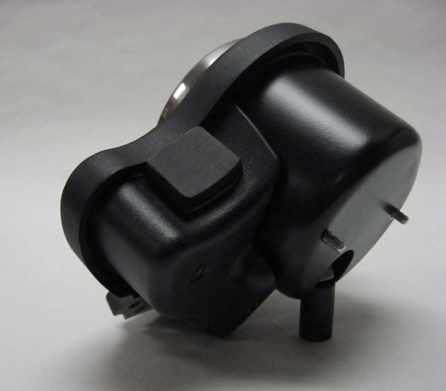
Here is the instrument cluster connector:

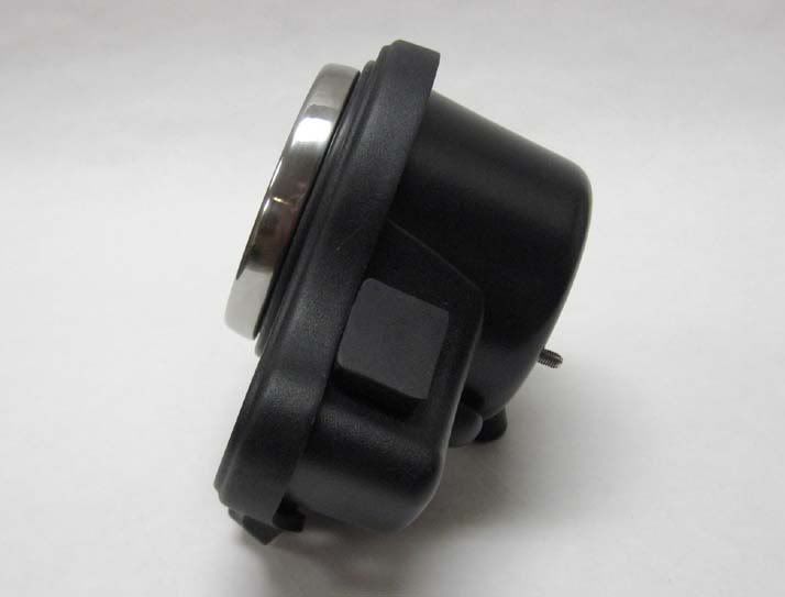
Here is the parking light connector:

SLICK METHOD:
Now, this is how I wired my bike, but I’m finicky about how things are done, that being said:
Find the black instrument housing connector inside the headlight housing and unplug it from the wiring harness.
Swing the top plastic bar across the back of the connector out of the way by using a small flat blade screwdriver to pry the tabs out on the sides. Do each side separately and the bar will swing away from the leads.
Remove the following leads one at a time, you need to push a paperclip (bevel end) or a real small screwdriver into the connector to release the pins


Now, solder the tach leads on as follows:
-Green wire on tach connects to red wire (tach signal) on connector (3rd from left in first photo)
-Red & Blue wires on tach both connect to red wire with blue stripe (instrument power) on connector (4th from left in first photo)
-Black wire on tach connects to Black wire with short silver stripes (instrument power ground) (top left in first photo)
The back of the metal connector is square and there is enough room to add an additional wire next to the existing wire. Solder the tach wires to the existing wires where they are crimped. It is easiest to tin both the wire and the connector separately, then make the final solder connection. It is also helpful to temporarily tape the connector to a small piece of wood when soldering in the headlight housing.
After all connections are soldered and the leads are pushed back into the plug it should look something like this:

I also installed a separate connector in the tach wiring so I could remove it if I ever wanted to, otherwise the tach is hardwired.
This is what I used for that, a three pin deans connector:

OLDER BIKE NOTE:
I have not done this, take with a grain of salt.
If you have an older bike without the red tach lead in the instrument connector, you should be able to run a wire down to the coil. Pull the plug off the coil that has a yellow wire with black stripe. Solder the green tach lead to it.
Hope this helps someone out.
:rockon:
There are two ways to do it.
First things first, disconnect the battery so you don’t short anything by accident, you have been warned!
DOWN AND DIRTY METHOD:
Cut the red tach signal wire in the instrument cluster connector and solder the wiring harness side to the green tach wire. Then solder the red & blue wires from the tach to the yellow wire going to the parking light, and the black wire from the tach to the black wire going to the parking light. If you connect to the headlight housing side of the connector you can still easily unplug the headlight.
Here is the instrument cluster connector:
Here is the parking light connector:
SLICK METHOD:
Now, this is how I wired my bike, but I’m finicky about how things are done, that being said:
Find the black instrument housing connector inside the headlight housing and unplug it from the wiring harness.
Swing the top plastic bar across the back of the connector out of the way by using a small flat blade screwdriver to pry the tabs out on the sides. Do each side separately and the bar will swing away from the leads.
Remove the following leads one at a time, you need to push a paperclip (bevel end) or a real small screwdriver into the connector to release the pins
Now, solder the tach leads on as follows:
-Green wire on tach connects to red wire (tach signal) on connector (3rd from left in first photo)
-Red & Blue wires on tach both connect to red wire with blue stripe (instrument power) on connector (4th from left in first photo)
-Black wire on tach connects to Black wire with short silver stripes (instrument power ground) (top left in first photo)
The back of the metal connector is square and there is enough room to add an additional wire next to the existing wire. Solder the tach wires to the existing wires where they are crimped. It is easiest to tin both the wire and the connector separately, then make the final solder connection. It is also helpful to temporarily tape the connector to a small piece of wood when soldering in the headlight housing.
After all connections are soldered and the leads are pushed back into the plug it should look something like this:
I also installed a separate connector in the tach wiring so I could remove it if I ever wanted to, otherwise the tach is hardwired.
This is what I used for that, a three pin deans connector:
OLDER BIKE NOTE:
I have not done this, take with a grain of salt.
If you have an older bike without the red tach lead in the instrument connector, you should be able to run a wire down to the coil. Pull the plug off the coil that has a yellow wire with black stripe. Solder the green tach lead to it.
Hope this helps someone out.
:rockon:


")