


You are using an out of date browser. It may not display this or other websites correctly.
You should upgrade or use an alternative browser.
You should upgrade or use an alternative browser.
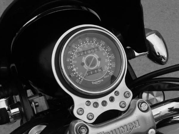
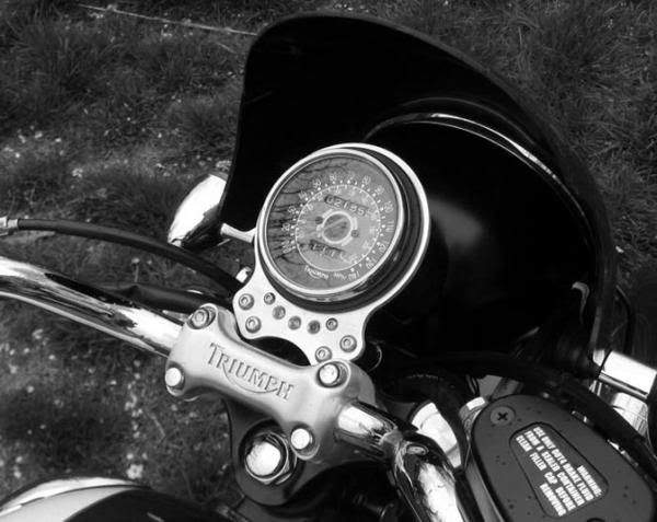
LED indicators w/OEM Speedo bracket
- Thread starter D9
- Start date
vintagebikefan
Scooter
Oh man, that's nice! You're brackets keep getting nicer and nicer.:worthy: I can imagine that with some ace bars, it would add nicely to the single speedo cafe/ boy racer look. I WANT ONE!!
D9
Vendor
VBF,
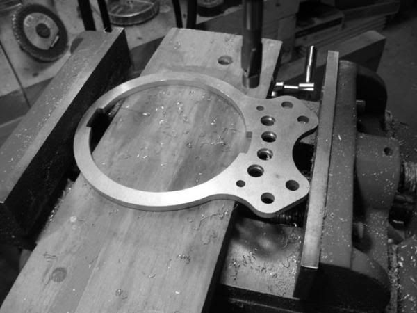
Appreciate the feedback... what's been holding these back is the
indicator housings... had to bang on 'em for quite awhile, but the first group
is finally getting close, have just a bit more machining, some filing &
finishing to do. Looking forward to seeing a finished bracket in black ano... will
post a pic as soon as it's done.
Cheers,
D9
IronButtJack
Scooter
I'm up for one in black. Let me know when they are available.
DavidC
Rocker
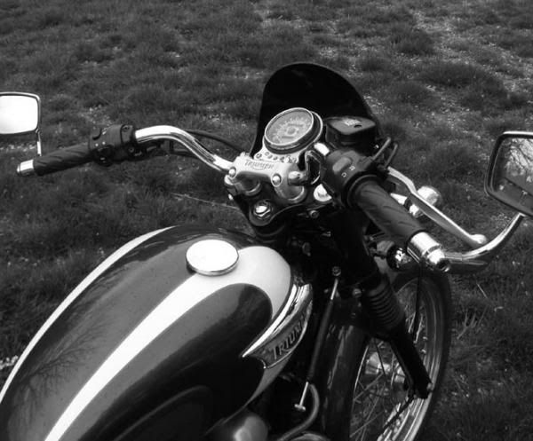
Eventually, I will have my speedo centered - like it ought to be - and the lights sensibly placed, preferably on the bottom in a line. Hey, I just realized my idea looks like wht you're making - or vice-versa.
Are the LED's a pain to fit on? Much electrical work?
I am interested in a lay flat bracket because they look SOOOO GOOD!
Are the LED's a pain to fit on? Much electrical work?
I am interested in a lay flat bracket because they look SOOOO GOOD!
D9
Vendor
IBJ - thanks & will do
DC - you'd be cutting off four (or three) OEM indicator lamps and attaching the LED lamps... need soldering gun, wire cutters, a little shrink wrap, two diodes... you'd need to solder the two small diodes to the turn signal indicator lamp (otherwise the lamp it won't blink)...
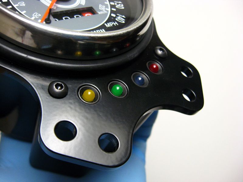
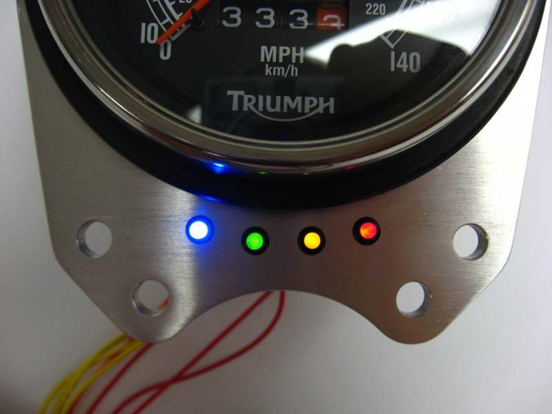
Disassembly of the OEM bracket and assembly of the LED bracket... not difficult. The bezels on the LED's are machined so they drop flush into the counter bored holes in the bracket then secured with a nut from the back... the indicator housing & backer attaches & assembles with 4 screws.
DC - you'd be cutting off four (or three) OEM indicator lamps and attaching the LED lamps... need soldering gun, wire cutters, a little shrink wrap, two diodes... you'd need to solder the two small diodes to the turn signal indicator lamp (otherwise the lamp it won't blink)...
Disassembly of the OEM bracket and assembly of the LED bracket... not difficult. The bezels on the LED's are machined so they drop flush into the counter bored holes in the bracket then secured with a nut from the back... the indicator housing & backer attaches & assembles with 4 screws.
D9
Vendor
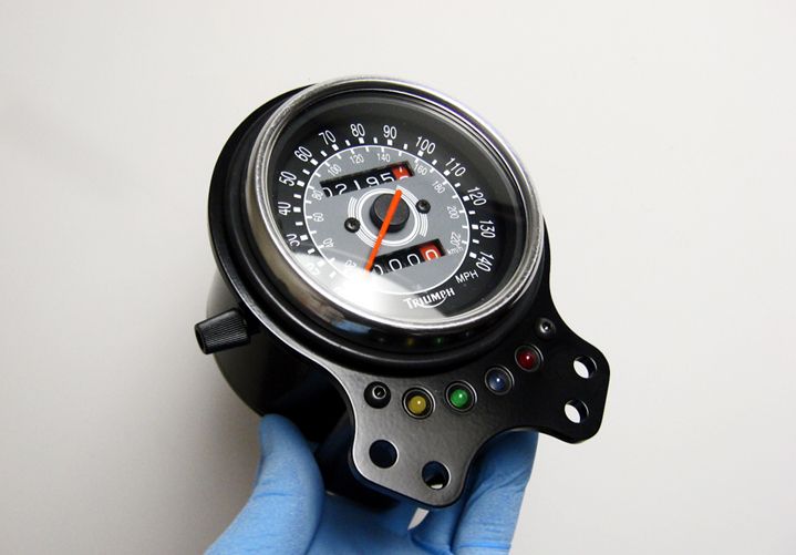
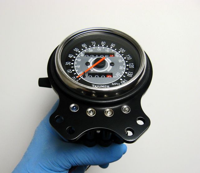
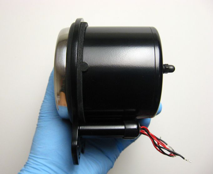
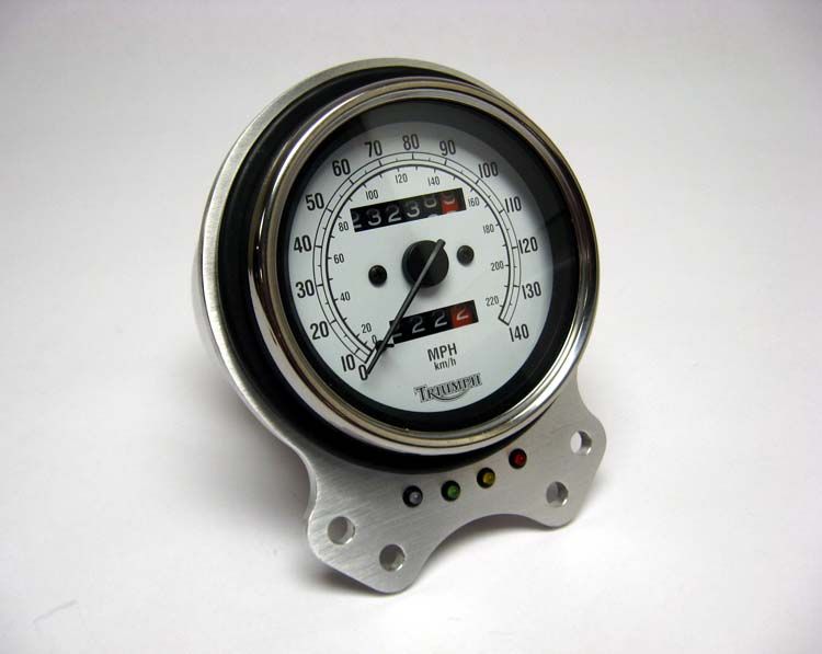
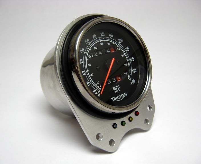
Two completed, slightly different versions of the 4-LED bracket - version 1 uses a single machined LED housing and backer, version 2 uses four separate machined tubes as LED housings. Also features a new non-tapered cup designed to minimize the slight gap between the LED housings and the tapered cup used on the prototypes.
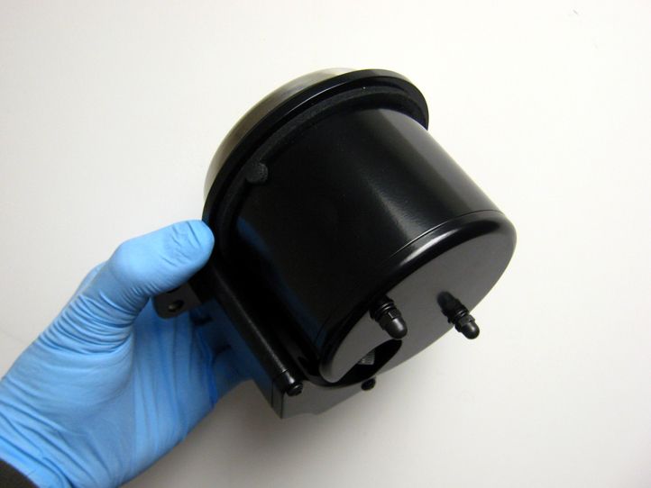
Why the two variants? I completed version 1 and then thought the face of the bracket might look better without the two M4 button head hex screws, but still needed way to enclose the LED's. Advantage of version 1 - the wiring all comes out of single port
on the back of the housing, neat & tidy & easier to hide. Advantage of version 2 - cleaner topside, but busier down below, although some careful use of black shrink wrap around the wiring will help...
Version 1
Version 2
Rest of the pics:
http://s192.photobucket.com/albums/z276/D9davidnyne/LED brackets/
Last edited:
Nick Morey
Rocker
More beautiful work, D9! Especially version 2.
IBJ - thanks & will do
DC - you'd be cutting off four (or three) OEM indicator lamps and attaching the LED lamps... need soldering gun, wire cutters, a little shrink wrap, two diodes... you'd need to solder the two small diodes to the turn signal indicator lamp (otherwise the lamp it won't blink)...
Disassembly of the OEM bracket and assembly of the LED bracket... not difficult. The bezels on the LED's are machined so they drop flush into the counter bored holes in the bracket then secured with a nut from the back... the indicator housing & backer attaches & assembles with 4 screws.
What size diodes, are needed to wire up these? I have 3mm LEDs, and found a radio shack part #on one of the wiring diagrams(276-1114) I couldn't find this on radio's site, but found some on a wholesalers site, which says it is a 2 1/2a 1000V risistance... Is this the correct size?? (ohms & volts & amps are so very confusing)